Cuprins
- Subject 2
- Initial data 3
- Chapter 1. Structural - functional analysis of a mechanical part .. 4
- CAD 2 PROJECT
- 2
- 1.1. 3D modeling .. 4
- 1.2. Part surfaces . x
- 1.3. Part and surfaces functions ... x
- 1.4. Material characteristics . x
- 1.5. Weight calculation . x
- 1.6. Geometrical characteristics ... x
Extras din proiect
3D modelling and structural-functional analysis of the CYLINDER part from the 6 CYLINDERS RADIAL ENGINE assembly.
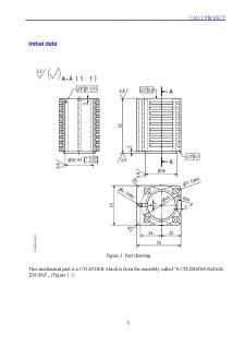
Initial data
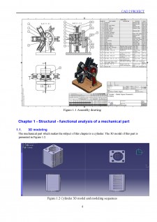
Figure 1. Part drawing
This mechanical part is a CYLINDER which is from the assembly called “6 CYLINDERS RADIAL ENGINE „ (Figure 1.1)
Figure 1.1 Assembly drawing
Chapter 1 - Structural - functional analysis of a mechanical part
1.1. 3D modeling
The mechanical part which makes the subject of this chapter is a cylinder. The 3D model of this part is presented in Figure 1.2.
Figure 1.2 Cylinder 3D model and modeling sequences
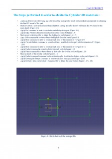
The steps performed in order to obtain the Cylinder 3D model are :
- Analysis of the received drawing and selection of the main profile which will contribute substantially to obtaining the final 3D model of the part
- Start in CATIA a new session in module called Part Desing and after that we will select the XY plane for the main sketch (Figure 1.3)
- Apply Pad command in order to obtain the main body of my part (Figure 1.4)
- Apply Edge Fillet to obtain the round corners of the radius 4 (Figure 1.5)
- Make a new sketch in order to obtain the sticking out part (Figure 1.6-1.7)
- Appy Hole command in order to obtain the big hole from the part (Figure 1.8)
- Apply Hole command in order to obtain a small hole of the diameter of 7 (Figure 1.9)
- Apply Circular Pattern command in order to obtain 4 small hole on the part with the diameter of 7 (Figure
1.10)
- Apply Hole command in order to obtain a small hole of the diameter of 4 (Figure 1.11)
- Apply Pocket command in order to obatin the small pocket (Figure 1.12)
- Apply Plane command in order to obtain an sketch for the circular pocket (Figure 1.13)
- Make a sketch of the circular pocket (Figure 1.14)
- Apply Pocket command command on the sketch in order to obtain the feature on the part (Figure 1.15)
- Apply Rectangular Pattern command in order to obtain 9 same pockets ( Figure 1.16)
- Apply the last 2 steps on the other 2 faces in order to obtain the same feature (Figure 1.17-1.18)
Bibliografie
References:
https://www.nedal.com/wp-content/uploads/2017/11/Nedal-alloy-Datasheet-EN-AW-6061.pdf https://www.bikar.com/fileadmin/user_upload/aluminium/bleche-platten/6061-complete-en.pdf
http://www.steelnumber.com/en/steel_alloy_composition_eu.php?name_id=1150 Dijmărescu M.R., CAD 2 Project_Work instructions_Chapter 1, 2017.
Preview document


Conținut arhivă zip
- 3D modelling and structural-functional analysis of the cylinder part from the 6 cylinders radial engine assembly..pdf