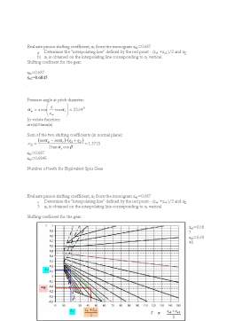
Extras din proiect
1.1 The history of the gears
Meshing gear teeth have been in use mankind for well over 3000 years.
Over 90% of man’s technical knowledge applicable to gearing has been developed since 1890, so the last 100 years.
The last 100 years can be divided into four periods. Which each period having approximately equal overall advancement in the gear art:
1. 1890 - 1930. The initial period in which gear manufacturing and gear engineering became recognized and established;
2. 1930 - 1960. Gear manufacturing and gear engineering became broad based; the art matured substantially;
3. 1960-1980. An area of considerable advancement in gear technology; the gear art became very sophisticated;
4. 1980 - the present. The old established gear art saw drastic changes as innovation in machinery design; computer control, new materials, and new lubricants came into being. The traditional way things used to be done in the gear shop or the gear design office has all tended to change substantially.
1.2 What is a gear?
A gear is a machine part, which transmits motion and force by means of successively engaging projections, called teeth. The smaller gear of a pair is called the pinion; the larger one, the gear.
When the pinion is on the driving shaft, the gear set acts as a speed reducer; when the gear drives, the set acts as a speed multiplier. The basic gear type is the spur gear, or straight-tooth gear, with teeth cut parallel to the gear axis.
Spur gears transmit power in applications utilizing parallel shafts. In this type of gear, the teeth mesh along their full length, creating a sudden shift in load from one tooth to the next, with consequent noise and vibration.
This problem is overcome by the helical gear, which has teeth cut at an angle to the center of rotation, so that the load is transferred progressively along the length of the tooth from one edge of the gear to the other.
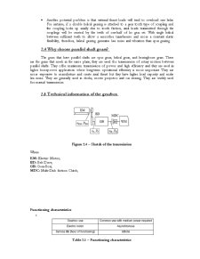
2.HELICAL GEARING DESIGN
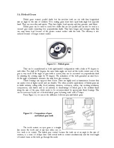
2.1. Helical Gears
Helical gears connect parallel shafts but the involutes teeth are cut with their longitudinal axis an angle to the axis of rotation. Two mating gears must have equal helix angle but opposite hand. They run smoother and quieter. They have higher load capacity and they generate axial thrust.
Helical gears can be used to mesh two shafts that are not parallel and can also be used in a crossed gear mesh connecting two perpendicular shafts. They have longer and stronger teeth, they can carry heavy load because of the greater contact surface with the teeth. The efficiency is also reduced because of longer contact surface.
Figure 2.1 – Helical gears
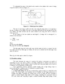
They can be manufactured in both right-handed configurations with a helix at 90 degrees to each other. For shaft at 90 degrees, the same helix angles are used ad the tooth contact area of the gear is very small. If the angle of gear teeth is correct, they can be mounted on perpendicular shaft by adjusting the rotating angle by 90 degrees. The inclination of the teeth generated an axial force. As the angle of inclination increases the axial force also increases.
Thrust bearings can support these forces. These are highly used in transmission because they are quieter even at higher speed and are durable. The other possible applications of helical gears are in textile industry, rolling mills, food industry, elevators, conveyors, cutters, clay working machinery, compressors, cane knives and in oil industry. A disadvantage of helical gear is the resultant thrust along the axis of the gear, which needs to be accommodated by appropriate thrust bearings. This can be overcome by the use of double helical gears by having teeth with a V shape.
From Figure 2.2, we can see the difference between spur and helical gears.
Preview document


Conținut arhivă zip
- The Gears.doc
Te-ar putea interesa și

În prima parte a acestei lucrări s-a proiectat un motor Diesel căruia i s-a aplicat procedeul de downsizing, ceea ce a presupus reducerea numărului...

1. New Tehnology Implementation 1.1 Argument Roland Gérard Barthes (12 November 1915 – 25 March 1980) was a French literary theorist,...

Să se studieze un avion de luptă - Curtiss P-40 Warhawk- Lucrarea va cuprinde: Cap Descriere etape Observaţii Termen de control 1 Prezentare...

Rezumat. Cuvinte cheie: maşină de lițat, cutie de viteze, cutie de pas,AutoCAD. Proiectul de față constituie documentația de execuție a cutiei de...

1.1 Introduction Nanomaterials are applications with morphological features smaller than one tenth of a micrometre in at least one dimension....

Capitolul 1 1.1 Istoria calculului la încovoiere pentru dantură 1.1.1. Introducere Primele calcule de rezistenţă sunt legate de construcţia...

Technical Specifications Also called: Volkswagen Dasher Volkswagen Quantum Volkswagen Santana Volkswagen Corsar Manufacturer: Volkswagen...

I. Introduction Vacuum casting is currently one of the most popular and flexible forms of rapid tooling for consumer products. It allows the...